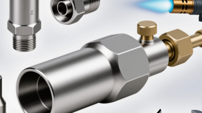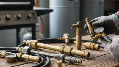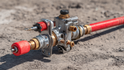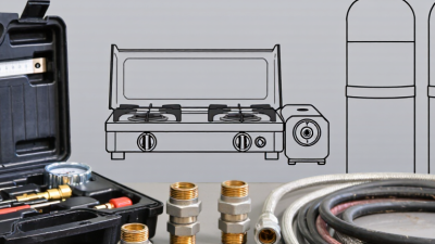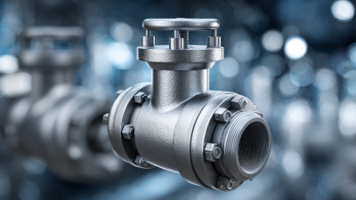
A propane nozzle looks simple, yet it controls a critical moment between stored fuel and useful energy. It connects a cylinder or dispenser to an appliance, vehicle, or approved filling point. Inside, a spring-loaded valve opens only when the connection is secure. A shutoff handle then controls the flow. Many models also include an automatic stop, swivel joint, or breakaway fitting.
The U.S. Energy Information Administration’s 2020 Residential Energy Consumption Survey found that roughly 5% of American homes used propane as their primary space-heating fuel. That figure shows the nozzle’s practical importance. It is a small component within a large energy system. NFPA 58, the Liquefied Petroleum Gas Code, addresses connector design, protection, installation, and safe handling. PERC guidance adds practical inspection advice for hoses, fittings, and dispensing equipment. Standards matter here.
Roy Willis, former president and chief executive officer of the Propane Education & Research Council, described propane as “a clean, affordable, and reliable energy source.” His statement explains the fuel’s appeal, but reliability still depends on the hardware. A worn seal can allow odorized gas to escape. A damaged connector can prevent proper valve engagement. That is not theoretical.
This guide explains what a propane nozzle does, how its internal parts cooperate, and why correct matching matters. It also separates dispensing nozzles from burner orifice nozzles, which are often confused. The distinction is easy to miss. Real installations are less tidy. Manufacturer instructions, inspection records, and trained service support should always guide decisions. A nozzle is not merely a handle. It is a controlled gateway.
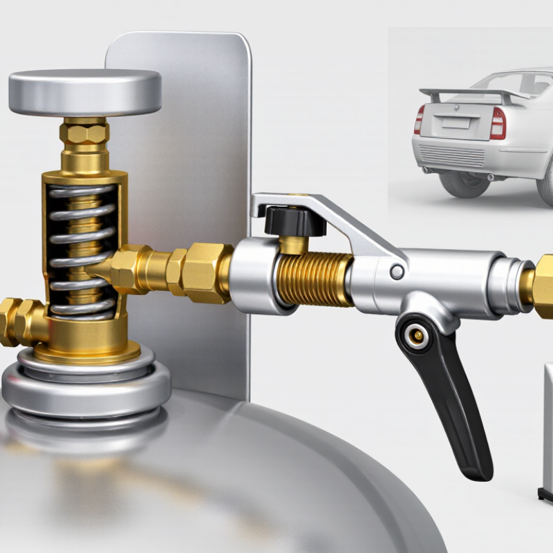
A propane nozzle is the controlled outlet where liquid or vapor propane enters a burner, appliance, or transfer line. Its small orifice regulates flow and shapes the gas stream for stable combustion. The nozzle does not create pressure; it uses the pressure already present in the LPG system. Correct sizing depends on pressure, temperature, fuel composition, and the appliance’s heat demand.
Propane’s physical properties explain much of its behavior. The NIST Chemistry WebBook lists propane’s normal boiling point near −42.1°C at atmospheric pressure. This means liquid propane can vaporize rapidly in ordinary outdoor conditions. NIST REFPROP property data indicate a vapor pressure of approximately 8.4 bar absolute at 20°C. That is not gauge pressure. The difference matters during inspection and troubleshooting.
As liquid passes through a restricted nozzle, pressure drops and some propane flashes into vapor. The escaping stream may cool the metal surface, sometimes producing frost around the fitting. Technicians should check for blocked or damaged orifices, because a tiny obstruction can create an uneven flame. NFPA 58 emphasizes approved components, leak testing, and protection from excessive heat. A pressure reading alone cannot prove safe operation. Temperature changes, hose condition, and regulator performance also affect the result. That detail is easy to overlook. A neat calculation can still mislead when the nozzle is dirty, misaligned, or installed with the wrong seal. Practical verification remains necessary.
Propane nozzles meter LPG through a controlled opening. At atmospheric pressure, propane boils at approximately −42.1°C. At 20°C, its saturated vapor pressure is about 8.4 bar absolute, so the nozzle and connected equipment must be rated for pressurized service.
How to read the chart: As propane temperature rises, its vapor pressure increases rapidly. A nozzle regulates the flow by converting pressure energy into a controlled gas or liquid flow through its orifice.
What Is a Propane Nozzle and How Does It Work?
A propane nozzle controls liquid fuel during transfer. The orifice is the precision opening inside the nozzle body. It regulates flow by creating a measured restriction. A larger opening can increase flow, but it may reduce control and raise pressure loss. Field technicians often inspect the orifice for dirt, frost, or distortion. Small defects matter.
The shutoff valve is the operator’s main control. When released, it stops liquid movement through a spring-loaded mechanism. The seal prevents leakage around moving parts and connection points. It must remain flexible, clean, and properly seated. A hardened seal can leak before anyone notices. That is an uncomfortable detail.
The breakaway coupling adds protection when a hose is pulled beyond its safe range. It separates at a designed force and limits fuel release through internal check valves. NFPA 58, the Liquefied Petroleum Gas Code, addresses emergency shutoff and hose protection requirements for dispensing systems. The World LPG Association’s 2024 statistical review reports global LPG demand above 330 million tonnes in 2023, showing why dependable transfer equipment matters across many settings. Still, standards do not replace inspection. A nozzle can appear clean while its seal is aging. Technicians should check valve movement, coupling condition, and visible damage before service, following the equipment manufacturer’s procedures and applicable local codes.
A propane nozzle is the controlled connection between a storage vessel and a receiving system. It guides liquefied petroleum gas through a sealed passage. Its internal valve helps prevent uncontrolled release when disconnected. The nozzle must match the receiving fitting exactly. Compatibility is not something to guess.
Connection begins before any pressurized transfer. Close the supply valve and remove dirt from both connection points. Inspect the nozzle body, threads, locking parts, and sealing ring. Look for cuts, flattening, cracks, or hardened rubber. A damaged seal can leak under pressure. Position the nozzle straight, then engage the coupling without force. Tighten it according to the equipment instructions. Over-tightening may damage the seal. Under-tightening may leave a dangerous gap.
The connection should feel secure, not improvised. A trained operator checks that the coupling is locked and the hose is supported. An approved leak-detection solution can reveal bubbles around the joint. Never use a flame to test for leakage. Correct any leak before opening the supply valve. Open the valve slowly, then watch the connection for movement, odor, frost, or bubbling. Stop immediately if anything seems unusual. It sounds simple. It is not. Even experienced workers can overlook a worn sealing ring when working quickly. That small oversight deserves more attention than speed. Follow the equipment manual, site procedures, and applicable safety requirements every time.
| Data Dimension | Typical Information | Purpose in the Connection | How to Verify | Safety Significance |
|---|---|---|---|---|
| Propane state during transfer | Liquefied petroleum gas is commonly transferred as a liquid under pressure, while vapor may be present above the liquid. | Explains why the connection must remain sealed before the valve is opened. | Confirm that the equipment is designed for LPG liquid or vapor service as specified by its documentation. | A small leak can release flammable vapor that may collect in low or poorly ventilated areas. |
| Nozzle connection type | Common designs use an O-ring, gasket, metal seat, flare seat, or another purpose-designed sealing interface. | Creates the pressure boundary between the nozzle and the receiving connection. | Identify the sealing surface from the applicable equipment documentation; do not assume that threads provide the seal. | Using the wrong interface can cause leakage, thread damage, or failure during pressurization. |
| O-ring or gasket condition | The seal should be clean, correctly seated, compatible with LPG, and free from cuts, flattening, cracks, swelling, or hardening. | Allows the sealing element to maintain contact as pressure is applied. | Inspect under good lighting and replace damaged or questionable seals with the specified type. | A defective seal may leak only after the line becomes pressurized. |
| Threads and mating surfaces | Threads should be clean, undamaged, correctly matched, and free from cross-threading; sealing faces should be smooth and unobstructed. | Provides alignment and, depending on the design, supports the sealing interface. | Start the connection by hand and stop if resistance or misalignment occurs immediately. | Cross-threading can prevent full engagement and may permanently damage the connection. |
| Thread sealant requirement | Some connections seal at a gasket or flare and require no thread sealant; other tapered pipe-thread connections may require an LPG-compatible sealant. | Prevents incorrect sealant use from interfering with the designed sealing method. | Follow the equipment instructions and use only sealant approved for LPG service where specified. | Unapproved tape or sealant can shed particles, obstruct valves, or be incompatible with LPG. |
| Hand tightening | The connector should initially engage smoothly by hand before any tool is used. | Helps confirm correct alignment and reduces the risk of cross-threading. | Turn the nut or coupling by hand until the sealing surfaces are properly aligned and seated. | Forcing a misaligned connection may create a hidden leak path. |
| Final tightening | The required torque is connection-specific and must come from the equipment documentation; there is no universal value for all propane nozzles. | Produces the intended compression or seating force without damaging the connector. | Use the specified tool and calibrated torque method when a torque value is provided. | Over-tightening can distort seals or threads; under-tightening can permit leakage. |
| Valve position before connection | The supply and receiving valves should remain closed during connection unless a procedure specifically states otherwise. | Prevents pressurized LPG from entering an incompletely secured connection. | Check the valve indicators and follow the approved transfer sequence. | Opening a valve before sealing can cause an uncontrolled release. |
| Leak-check medium | Use an approved, non-corrosive leak-detection solution or an instrument suitable for LPG service. | Reveals escaping gas at the connection after controlled pressurization. | Apply the solution to the joint and observe for continuously growing bubbles, or use the approved detector. | Never use a flame to test for leaks. |
| Initial pressurization | Pressurize gradually according to the approved operating procedure rather than opening the valve abruptly. | Allows the seal and connection to be checked under pressure before full transfer begins. | Monitor the joint, hose, fittings, and pressure indication during the initial pressure rise. | A gradual pressure increase helps limit the consequences of an improperly seated seal. |
| Ambient temperature consideration | Propane vapor pressure rises as temperature increases; at approximately 20 °C, saturated propane vapor pressure is about 8.4 bar absolute. | Shows why a connection may experience substantial pressure even when the equipment is not being actively pumped. | Use pressure ratings and operating limits specified for the actual equipment and temperature range. | Heat can increase internal pressure and worsen the effect of a weak seal. |
| Connection acceptance criteria | Correctly matched, fully seated, mechanically secure, free of visible damage, and leak-free during the required check. | Confirms that the nozzle is ready for the next transfer step. | Document the inspection and leak-check result when required by the operating procedure. | If any criterion fails, isolate the supply and correct the connection before continuing. |
Important: Connector designs, materials, pressure ratings, torque values, and inspection intervals vary. Always follow the applicable equipment instructions, LPG transfer procedure, and local safety requirements.
A propane nozzle controls gas delivery through a small opening called an orifice. This opening is not just a passageway. Its diameter determines how much propane can enter the burner under a given pressure. A smaller orifice restricts flow and produces a smaller flame. A larger orifice allows more gas to pass.
Pressure also matters. The regulator supplies propane at a controlled pressure, while the nozzle creates resistance. Together, they shape the flow rate. In practical inspections, I look for a stable blue flame, even burner sound, and clean ignition. Yellow tips, lifting flames, or soot can suggest incorrect flow, blocked passages, or poor air mixing. The nozzle alone may not be the problem.
I once assumed that a wider opening would simply improve heating. That assumption was wrong. Excess gas can create incomplete combustion and increase carbon monoxide risk. A restricted opening may cause weak heat or delayed ignition. Orifice size must match the appliance design, fuel type, and operating pressure. Never enlarge an orifice with a drill or substitute an unverified part. Shut off the supply before inspection, and use a qualified technician when measurements or replacement are uncertain. Tiny differences can change performance.
A propane nozzle connects the supply hose to a container’s fill valve. Inside the assembly, a shutoff mechanism controls liquid flow during filling. The process depends on more than the operator watching a gauge. NFPA 58 uses an 80% container-fill limit, leaving room for propane to expand as temperatures rise.
That space matters. A container filled completely with liquid propane could develop dangerous pressure during heating. Many approved containers use an internal float gauge or automatic stop valve. When the liquid reaches the permitted level, the valve restricts or stops filling. The nozzle may click, resist movement, or show a noticeable change in flow. Small details matter.
Excess-flow protection addresses a different hazard. If a hose breaks or a connection separates, the sudden increase in flow can force the valve closed or sharply restrict discharge. It is not a guaranteed seal. A damaged valve, incorrect connection, or trapped debris can reduce its performance. I always inspect the coupling, gasket, and valve area before connecting. Gloves help, but they cannot replace training.
NFPA 58 also expects suitable equipment, correct procedures, and competent personnel. The 80% limit should never be bypassed by guessing from pressure alone. Pressure changes with temperature and does not reliably show container fill level. A trained technician verifies the container, nozzle connection, and shutoff response before releasing the equipment for use.