
How to Assemble a Thermoforming Mold in 2026?
Thermoforming Mold Assembly demands accuracy, patience, and practical judgment. In 2026, modern molds combine CAD modeling, CNC machining, thermal control, and detailed inspection. Yet technology cannot correct a poorly aligned mold half. Small errors still create uneven wall thickness, webbing, weak corners, or difficult part release.
John G. Beaumont, a respected plastics-processing author and consultant, offers a useful principle: “Good tooling begins with controlled material flow, not with shortcuts.” His observation remains relevant during mold assembly. Technicians must inspect the mold base, forming surface, vents, cooling channels, fasteners, and locating features before production begins. A clean bench helps. A calibrated torque wrench matters. Even a tiny particle between mating surfaces can distort alignment.
This guide follows a practical assembly sequence. It explains how to verify component identity, install inserts, connect cooling lines, protect vent openings, and confirm the mold’s reference position. It also addresses trial heating and first-part inspection. These steps sound straightforward, but real workshops are rarely perfect. Drawings may contain unclear notes. Components may have minor machining variation. Operators may overlook a blocked vent after cleaning.
That uncertainty deserves attention.
Reliable Thermoforming Mold Assembly is not only about following instructions. It requires recording measurements, questioning unexpected resistance, and correcting problems before the mold reaches full production. The process may feel slower at first. In practice, careful preparation usually prevents longer stoppages, damaged tooling, and inconsistent parts. This 2026 approach values precision, traceability, and informed human judgment.
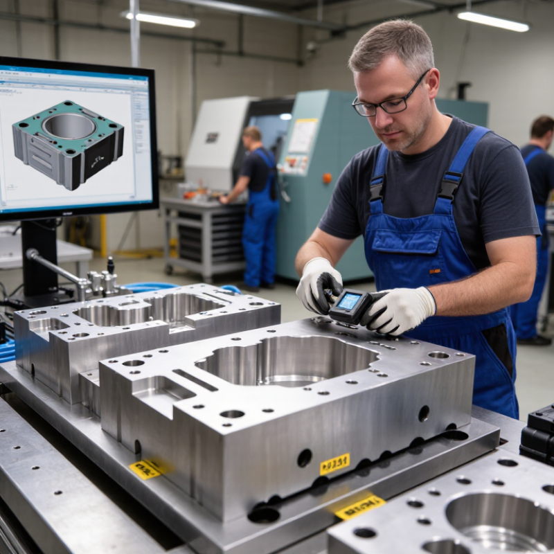
Before assembling a thermoforming mold in 2026, define its production requirements clearly. Specify the polymer, sheet thickness, part dimensions, expected cycle time, and annual volume. Mold design must also reflect forming temperature, shrinkage, draft angles, vent locations, cooling paths, and trimming access.
Published market estimates show strong demand. Grand View Research valued the global thermoforming market at approximately USD 16.35 billion in 2023, with a projected 5.8% annual growth rate through 2030. Another 2024 industry assessment reported different market values and growth assumptions. That difference matters. It shows why internal production data should guide mold decisions, rather than market forecasts alone.
Assembly should begin with a verified mold base, aligned inserts, secure fasteners, and accessible cooling connections. Vent holes should be small enough to avoid visible marks, yet effective enough to prevent trapped air. The mold surface needs a defined finish, because texture affects release and product appearance. Use inspection records for cavity dimensions, flatness, cooling flow, and clamp alignment. ISO 20457 provides useful guidance for plastics mold construction and dimensional control. Still, it does not replace practical trials. A mold may pass inspection and form poorly. Our common mistake is treating the first successful sample as proof of full readiness. Run repeated cycles, measure wall thickness, and record defects before approving production.
How to Assemble a Thermoforming Mold in 2026
A reliable thermoforming mold begins with a clean, rigid mold base. Check its flatness before installing anything. Small height errors can create uneven wall thickness and weak corners. Secure the base to the machine using suitable clamps, then confirm that the centerline matches the forming station.
Install the forming surface carefully. Remove dust, sharp edges, and machining residue first. Align the surface with dowels or other locating features. Check vent holes for blockage, because trapped air can distort fine details. Connect cooling channels and inspect every fitting for leaks. Add heaters, temperature sensors, ejector pins, or vacuum connections only when the design requires them. I once rushed this stage and found a blocked vent after several test cycles. That delay was avoidable.
Tips: Keep a simple assembly record. Note torque values, cooling pressure, and sensor positions. Use a soft brush around polished surfaces. Do not force mismatched components. A perfect first setup is uncommon, so inspect the first formed part closely. Measure corners, flange edges, and surface detail. If the result looks acceptable, check it again. Visual approval alone can miss uneven cooling. Some assemblies still need adjustment after testing, and that is not a failure; it is useful process information.
A practical assembly reference for preparing a thermoforming mold, integrating forming components, and verifying production readiness.
| Assembly Stage | Required Component or Feature | Typical Specification or Target | Assembly Action | Verification Method | Common Risk to Control |
|---|---|---|---|---|---|
| 1 | Mold base | Rigid, flat support plate sized to the machine platen and mold footprint | Clean the base, remove burrs, and confirm that mounting holes align with the machine layout. | Use a straightedge, feeler gauge, and dimensional inspection of mounting locations. | Uneven support can cause mold deflection, poor thickness distribution, and incomplete forming. |
| 2 | Forming surface | Surface profile matched to the finished part, with smooth transitions and no sharp unintended edges | Install the forming surface or cavity onto the base without forcing or distorting the profile. | Check the profile against the approved CAD model, template, or dimensional drawing. | Incorrect geometry may create wrinkles, webbing, thin corners, or part-release problems. |
| 3 | Draft angles | Often approximately 1° to 3° per side, depending on geometry, texture, and release direction | Confirm that vertical walls include adequate draft before final fastening. | Measure critical walls with an angle gauge or inspect the 3D model and section drawings. | Insufficient draft can lock the part on the mold and damage both the part and the mold surface. |
| 4 | Vacuum channels | Distributed around deep draws, corners, ribs, and other areas where trapped air may remain | Connect channels to the vacuum manifold and keep passages free of chips, sealant, and debris. | Apply low-pressure air or vacuum and confirm flow at all intended outlet locations. | Blocked or poorly positioned channels can cause incomplete detail and air pockets. |
| 5 | Vacuum ports and manifold | Ports sized for the mold volume and connected with short, sealed pathways where practical | Fit ports, hoses, valves, and the manifold; tighten connections without damaging threads. | Perform a leak test and observe vacuum decay after isolating the mold. | Leaks reduce forming speed and may produce uneven replication of the mold surface. |
| 6 | Vent holes | Small openings located at pockets, corners, high points, and deep-draw zones | Drill or install vents according to the design, then deburr the openings on the forming side. | Inspect each vent visually and verify unobstructed airflow from the mold surface. | Oversized vents may leave marks; undersized or blocked vents may trap air. |
| 7 | Heating and cooling provisions | Temperature-control channels or heat-resistant construction appropriate to the forming cycle | Connect cooling lines or confirm heating elements, insulation, and thermal barriers are secure. | Pressure-test fluid channels and check temperature uniformity during a dry run. | Temperature gradients can cause warpage, inconsistent wall thickness, and unstable cycle times. |
| 8 | Parting line and trim reference | Clearly defined line that supports part removal and provides a repeatable trim datum | Align the mold halves or trim features and verify that no unintended step exists at the parting line. | Use a profile gauge, visual inspection, and a sample trim check. | A misaligned parting line can create flash, uneven edges, or difficult downstream trimming. |
| 9 | Locating and fastening hardware | Positive locating features with fasteners suitable for the mold material and expected loads | Install dowels, keys, bolts, washers, and retainers; tighten progressively in a cross pattern. | Check alignment, thread engagement, torque records, and clearance from moving components. | Loose or misaligned hardware may shift the mold, damage threads, or interfere with machine movement. |
| 10 | Release and surface finish | Smooth, clean finish appropriate for the plastic sheet, texture, and required part appearance | Polish or texture approved areas, remove abrasive residue, and apply only a compatible release treatment when required. | Inspect with controlled lighting and compare against the specified surface-finish requirement. | Roughness, contamination, or excess release agent can transfer defects to the formed sheet. |
| 11 | Sensors and reference points | Temperature, pressure, position, or alignment references located where they represent the process accurately | Secure sensors, protect wiring, label connections, and maintain access for calibration. | Confirm signal response, sensor identity, cable routing, and calibration status. | Incorrect sensor placement can cause false process readings and unstable quality. |
| 12 | Final assembly inspection | All components installed, surfaces clean, utilities connected, and safety clearances maintained | Complete a documented inspection before placing the mold into production service. | Use a checklist covering dimensions, vacuum performance, utilities, fasteners, and machine clearance. | Skipping the final inspection increases the likelihood of leaks, collisions, scrap, and unplanned downtime. |
Align and Secure the Mold Components on the Assembly Platform A stable assembly platform is the foundation of accurate thermoforming mold assembly. Clean the platform, mold base, and locating surfaces before positioning any component. Even a thin chip can create a measurable tilt. Check platform flatness with a calibrated straightedge and feeler gauge. Record the readings for traceability.
Place the mold base against its defined datum edges. Install cavity plates, support blocks, and guide components without fully tightening the fasteners. This allows controlled movement during alignment. Use dowel pins only after the mating surfaces sit evenly. Measure the mold centerline with a dial indicator or digital measurement arm. Check both lengthwise and crosswise directions.
The first alignment is rarely perfect. That is normal. Adjust with verified shims, not improvised metal scraps. Confirm that vacuum ports, cooling channels, and access holes remain unobstructed. Tighten bolts gradually in a cross pattern. Follow the approved torque values from the engineering drawing. Over-tightening can distort thin plates and change the forming surface.
After securing the components, sweep the reference surfaces again. Rotate moving parts by hand and watch for binding. A small error may disappear during a cold check but appear after heating. For that reason, record clearances at room temperature and review expected thermal expansion. I have seen reliable assemblies fail because one final measurement was treated as unnecessary. Calibration records, photographs, and signed inspection results make the setup easier to verify and repeat.
A reliable thermoforming mold starts with clean, accurately matched components. Before fitting anything, inspect sealing faces, drilled passages, and mounting points for burrs or damage. Keep the mold surface smooth, but do not polish away designed vents or texture. Small errors can create uneven wall thickness.
Install heating elements with even spacing across the forming area. Use measured resistance checks before connecting power. Cooling lines should follow the thickest mold sections, where heat remains longest. Secure every hose away from moving parts. Keep it accessible. A blocked cooling circuit can delay production and distort corners.
Connect the vacuum manifold with short, balanced paths whenever possible. Place vacuum ports near deep features, but protect them from material blockage. Test the system under vacuum and watch for pressure loss.
For release, confirm that ejector pins, air channels, or mechanical lifters move without scraping the formed part. I once overlooked a slightly misaligned pin, and it marked several test pieces. That mistake matters. Run a dry cycle before heating, then record temperature, cooling time, vacuum level, and release force. These records support repeatable adjustments and help technicians identify problems before full production.
After assembling a thermoforming mold, inspect every working surface under strong, angled light. Check the cavity, vents, vacuum ports, cooling channels, seals, and alignment pins. Remove small burrs that could mark the heated sheet or restrict airflow. A straightedge can reveal gaps across the mold base. Pay close attention to corners, where machining errors often remain hidden.
I test the cooling circuit before forming any parts. Stable pressure and dry connections help expose blocked passages or leaking fittings. Then I run a vacuum test with the mold empty. A slow pressure drop usually indicates a damaged seal, loose plug, or poorly seated hose. It is easy to blame the vacuum pump too quickly. The mold may be the real problem.
The first forming trial should use the intended sheet thickness and a controlled heating profile. Inspect wall thickness, corner definition, surface marks, and unwanted webbing. Fine-tune vent size, vacuum timing, sheet temperature, or plug-assist position in small steps. Change one variable at a time, and record each result beside the sample. I once adjusted temperature when the actual issue was uneven cooling. That mistake cost several trial cycles. Do not ignore small differences. A slight wrinkle near one corner can reveal poor air evacuation, uneven clamping, or an inaccurate mold surface. Record the correction.
